Wheel guidance mechanisms - Dependent support
- the required space above the axle for the support stroke, if the support stroke is long, the passenger or load part must be additionally sacrificed due to the placement of the support system
- large unwavering ground, especially if the differential is in the axle housing
- the vertical load changes during acceleration
- inability to adjust the geometry
- the system is small in height
- large axle movements are possible (field use)
- the track of the wheels, the retraction of the wheels and the inclination of the wheels do not change during the simultaneous uniform vertical movement of both wheels of the same axle, which enables a small wear of the tires and safe keeping of the direction
- the inclination of the wheels does not change when turning, so it is possible to transfer the lateral force more evenly with the help of both tires of the same axle
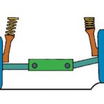
In the 30s, French car maker De Dion found a way to reduce unshakable mass by fixing the rear axle drive elements to the body rather than the axle itself. This type of rigid drive axle has long been used in sports vehicles but has been abandoned due to the massive use of independent suspension systems. During the development of Mercedes' Smart model in 1996, designers sought a solution for compactly positioning the powertrain over the rear wheels. A solution was found to a U-shaped link connecting two wheels. The De Dion shaft is shown in Figure 2.

Figure 2. De Dion shaft
Rigid shafts with longitudinal leaf motions
Most rigid suspension systems use longitudinal leaf motions. Depending on their construction, they can provide partial or complete shaft control. Extra clamps are often used to limit the lateral or longitudinal forces acting on the shaft. Leaf motors offer several advantages, including small assembly heights, take up little space, and create low loads at the points where the motors attach to the body, because the link points are at a considerable distance from each other. Leaf motions also have several disadvantages, such as high mass. , friction, tendency to twist (when accelerating or braking leaf springs take the form of letter S), bouncing wheels when changing load (Figure 3). Due to all these shortcomings, leaf motions cannot provide the comfort required in today's passenger vehicles.

Figure 3. Defective rigid shafts with leaf motions
-
The Hotchkiss axle (Figure 4) is a well-known type of rear drive axle that has elliptical leaf motors, and is still used today on many SUVs and light commercial vehicles. This solution has no additional reliance on support. The lateral and longitudinal movements of the wheels are controlled only by leaf motions.
Transport vehicles and smaller combination vehicles often have higher axle loads than the passenger vehicles on which they are based. To withstand the load, these vehicles use rigid, leaf-mounted axles that guide the wheels. This type of axle does not require any additional suspension mounting and is the simplest and most economical solution for non-drive rear axles. However, this solution does not leave much room for further enhancements as softer (longer) leaf motions would result in less lateral steering control and increased twist.
")
Figure 4. Rear drive axle with leaf motors (1995 Opel Campo)
Rigid shafts with coil springs
The elements controlling the movement of the rigid rear axle must enable translation in the vertical direction and rotation around the longitudinal axis of the vehicle. Light, friction-free coil springs do not play a role in controlling the lateral or longitudinal movement of the axle. The lateral forces between the body and the axle are transmitted by means of a Panhard rod or some other connection. Moving the Panhard rod causes the side of the vehicle body to move laterally during vertical movement of the axle. Lateral displacement can be eliminated by using Watt clamps to control lateral displacement (blue elements in Figure 5). The axle can be attached to the body using one three-point connection and two longitudinal connections with two attachment points each. An example of using a rigid axle with helical springs and longitudinal links is the Ford Mustang.
")
Figure 5. Non-drive rigid shaft with Watt clamps and two longitudinal clamps (1997 Chrysler PT Cruiser)
The Ford rigid axle with four links and coil springs was used very often until the 70's. The differential is housed in a rigid shaft housing and is attached to the body with two longitudinal clamps on the bottom and two sloping clamps on the upper side. Braking and acceleration moments are transferred between the body and the axle using the upper and lower clamps. The lateral forces that occur on the axle are controlled by slanting clamps. This solution is shown in Figure 6.
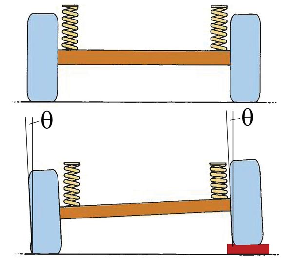
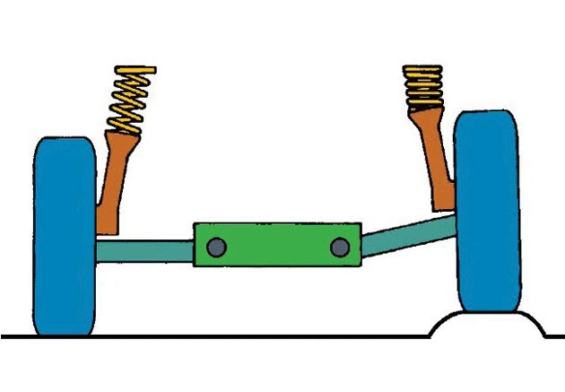
") Figure 6. Rear 4-Axle Drive Shaft (1970 Ford Taunus) When a rigid axle with longitudinal links crosses the bump so that only one wheel is moved vertically, the axle will also receive a steering function ("self-steering"). This tendency will be even more pronounced if the pivot axis is closer to the axle. This effect (Figure 7) causes unstable guidance when crossing over unevenness.
Figure 6. Rear 4-Axle Drive Shaft (1970 Ford Taunus) When a rigid axle with longitudinal links crosses the bump so that only one wheel is moved vertically, the axle will also receive a steering function ("self-steering"). This tendency will be even more pronounced if the pivot axis is closer to the axle. This effect (Figure 7) causes unstable guidance when crossing over unevenness.

Figure 7. Solid axis self-steering
Another disadvantage of rigid axles is the change in vertical load on the wheels during acceleration. If the differential is in the rigid shaft housing, the driving torque from the engine is absorbed at the centers of the tire contact area with the pad, resulting in a change in the vertical load on the tire. In the example of Figure 8, the driving torque M would further load the rear left wheel and the load would be less on the right wheel. In the right curve, the right wheel could slip, which could result in a loss of lateral force on the entire axle and thus cause unwanted slipping of the rear of the vehicle and loss of stability.
")
Figure 8. Vertical load change due to driving torque (rear view of vehicle)
The coil springs, which are most commonly supported by the lower rigid shaft links, provide a higher degree of comfort. The kinematic properties of the axle can be influenced by changing the geometric orientation of the mounted clamps. By kinematic optimization of the binding site, improvements can be made with respect to the position of the longitudinal axis of rotation, the degree of submergence or elevation during braking and acceleration, and the degree of self-control when crossing the unevenness with a single wheel. Figure 9 shows the various structural solutions of a rigid axle suspension.
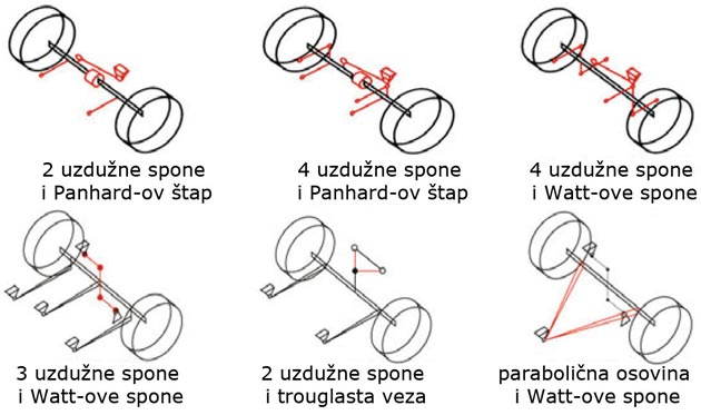
Figure 9. Different solids solutions with rigid shaft
For rigid shafts, the two upper links can be replaced by a single triangular link with three points of attachment. Control of the lateral movement of the body relative to the rigid axle is solved by installing a Panhard rod (Figure 10) or Watt clips.

Figure 10. Rear drive shaft with three clamps and Panhard rod
Text by Vanja Dragosavljevic
Retrieved from: www.vrelegume.rs


Hi there, I am Mladen and I am an auto enthusiast. I started this blog years ago to help like minded people share information about latest cars, car servicing ideas, used car info, exotic cars, and auto technology. You will find helpful articles and videos on a wide variety of cars - Audi, Mercedes, Toyota, Porsche, Volvo, BMW and much more. Ping us if you have anything cool to share on latest cars or on how to make older cars more efficient, or just want to say hi!
Mladen
Hi there, I'm Mladen and I'm an auto enthusiast. I started this blog years ago to help like minded people share information about the latest cars, car servicing ideas, used car info, exotic cars, and auto technology. You will find helpful articles and videos on a wide variety of cars - Audi, Mercedes, Toyota, Porsche, Volvo, BMW and much more. Ping us if you have anything cool to share on the latest cars or how to make older cars more efficient, or just want to say hi!