Suspension systems

Suspension systems
If you were wondering what is between the bodywork and asphalt, we give you the answer in the following lines
Suspension systems are mechanisms and elements whose task is to transfer all forces and torques that occur between the wheels and the ground when moving the vehicle onto the frame or body, with the greatest possible mitigation of impact loads, as well as ensuring the stability of the vehicle, especially when cornering. The movement of the vehicle on the ground causes oscillations of the vehicle as well as the masses in or on the vehicle. The higher the speed and mass of the vehicle, the higher the oscillations. The acceleration of the masses caused by oscillations can break the contact of the wheel with the substrate. Disruption of the wheel contact with the substrate loses control and braking and can lead to loss of vehicle stability. In well-designed suspension systems, the dynamic forces are less transmitted to the passenger compartment of the vehicle and passengers, so driving will not cause fatigue and discomfort for the occupants when driving.
The suspension system is a complex system that generally consists of four separate systems: wheel guidance mechanisms, elastic supports, damping elements and stabilizers.
The task of the wheel guidance system is to ensure that the relative movement of the wheels is as favorable as possible relative to the frame or body of the vehicle. The elements of the wheel guidance system must also ensure that horizontal forces and moments are transmitted from the wheel to the frame or body of the vehicle. Wheel guidance systems will be explained in more detail in a future issue.
The task of resilient supports is to transmit vertical forces to the frame or body of the vehicle and to provide the greatest possible mitigation during the transfer of vertical forces, ie. to minimize impact loads. Elastic supports should protect the vehicle structure and passengers from unpleasant vertical movements and rotations about the vertical and horizontal axes of the vehicle. Elastic supports are made in several ways: leaf, spiral or torsion springs, rubber or rubber-metal elastic elements, hydraulic, pneumatic or hydropneumatic springs.
Leafy motions

Figure 1: Trapezoidal and parabolic motions
Leaf motions are elastic elements that bend under the action of force. They consist of longitudinal springs (sheets) of rectangular or elliptical shape which are stacked on top of one another. The leaves are secured so that they do not move longitudinally relative to one another, and they also ensure that the leaves do not move sideways relative to one another. The main advantage of leaf motors over other solutions is that they allow not only the function of an elastic support, but can transmit longitudinal forces (driving and braking force) to the body or frame of a vehicle. Due to the friction between the individual leaves, the leaf spring also acts as a damping element. Leaf motions are a relatively inexpensive yet reliable and robust solution. Today, a combination of rigid axle and leaf motors can only be encountered on a small number of passenger vehicles, mainly sports delivery vehicles (SUVs). In commercial vehicles, this solution is still widespread. The suspension solution with coil springs is shown in Figure 1.
Spiral springs

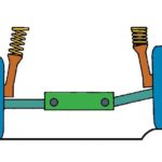
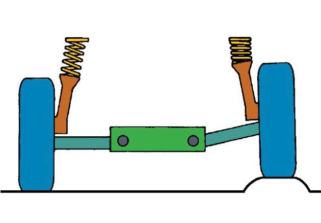
Figure 2: Coil springs
The coil springs can receive forces exclusively in the axial direction, which is why they are not used to receive lateral and longitudinal loads. For this reason, spiral spring structures always comprise longitudinal and transverse abutments which are connected at one end to the lower spring support and the other to the body. In this way, the persistent levers receive longitudinal and transverse loads, while the coil springs receive vertical loads. The coil spring suspension system is shown in Figure 2.
The advantages of coil springs over leaf motors are less weight, longer life, no friction, simpler construction, lower cost and easier maintenance. The disadvantages mentioned above are the inability to transmit longitudinal forces and the absence of damping effect. These disadvantages result in a greater degree of complexity of the coil spring system than the leaf spring system, as separate damping and guidance systems must be added to the elastic support system. Spiral springs are made of circular steel wire and are most commonly used as the basic elastic support.
Torsion springs

Figure 3: Different designs of torsion springs
Torsion springs are also used as a basic elastic support. They can be positioned transversely or longitudinally with respect to the vehicle but always in a horizontal plane. Torsion springs are elastic elements made of straight rods of circular cross section, composed of one or more bundled pieces. The disadvantages of torsion springs are the large lengths they require, the need for a special guiding mechanism and the inability to damp. Figure 3 shows torsion springs in one piece and in bundles.
Rubber supports

Figure 4: Example of rubber mounts
Rubber supports are used for various purposes and in different dimensions on vehicles. The tire has good damping characteristics of oscillations and vibrations, light weight, simple construction and acceptable service life. Rubber supports are made in combination with plastic and metal bushings. Rubber supports are often used to elastically connect the metal elements of the suspension system, e.g. the coupling of the guides with body elements or damping elements with the body. The rubber mounts are rounded in Figure 4.
Pneumatic elastic supports
Pneumatic elastic restraints are used for vehicles in which the load is changing over a wide range (buses, trucks and trailers) and in higher class passenger vehicles where designers want to provide additional comfort (Citroen, Range Rover, Mercedes…).
Pneumatic elastic elements are made of elastic polyurethane rubber. The airbags replace the springs as damping elements in the suspension system. Each individual airbag is connected by a valve that controls the amount of air contained in the airbag. The valves are connected to the compressor and to a small tank of pressurized air. By opening and closing the valve, the amount of air in each individual airbag can be adjusted. By reducing the pressure in the airbags, the distance between the vehicle and the ground is reduced and vice versa. Since the pneumatic elements do not have the ability to transmit longitudinal and transverse forces, they are combined with the guiding elements. One of the reasons for using air suspension is the degree of comfort, air suspension transmits significantly less vibration from the road surface than conventional systems.
Hydropneumatic systems

Figure 5: Illustration of a part of a hydropneumatic suspension system
In hydropneumatic suspension systems, the hydraulic sphere plays the role of an elastic element. The upper sphere contains gas (usually nitrogen) under pressure above the diaphragm. Through the diaphragm, gas is pressurized by the hydraulic fluid, and when the pressure drops the gas returns the hydraulic fluid to its previous position. This phenomenon is similar to spring compression and stretching. Hydropneumatic elastic elements are similar to pneumatic ones, the difference being that in addition to compressed air, the system contains incompressible fluid. The vertical movement of the wheels is transmitted to the fluid and through it to the diaphragm above which the gas is located. Shifting the wheel causes the gas to compress and the system then behaves similarly to a pneumatic one. This type of springs can also serve as a shock absorber and level regulator. Figure 5 is an illustration of a part of a hydropneumatic suspension system.
Damping elements (shock absorbers)

Figure 6: Suspended and unabated mass
When the vehicle encounters uneven ground, the elastic and damping elements are compressed. The resulting impact is absorbed by the suspension system. Suspension system prevents contact suspension and non-suspension of mass (Suspended mass means all parts whose weight loads elastic elements (wheels, tires, control system elements, individual elements of the suspension system, partially axles and most commonly elements of the braking system). below the elastic elements, whose weight does not load the elastic elements, are called unbound mass). However, the springs will tend to stretch again thus releasing the energy stored in them. Damping elements are used to minimize and eliminate these oscillations as quickly as possible. The suspension and non-suspension of mass oscillate at different frequencies. Figure 6 shows how the damping element (red curve) reduces the influence of oscillations due to the uneven substrate (blue curve, non-damped oscillations).
Due to the presence of elastic supports in the suspension system, it is normal for oscillations to occur during vehicle movement. Oscillations are uncomfortable for passengers inside the vehicle but can also cause more serious dynamic loads and shocks and the task of the suspension system is to attenuate the oscillations as much as possible. Other elements of the suspension system, not just dampers, are also involved in damping oscillations. Today, hydraulic shock absorbers are the most commonly used. The principle of operation of the hydraulic shock absorber is based on the conversion of kinetic energy into thermal energy due to friction within the fluid, ie. oil contained in the shock absorber. In modern vehicles, telescopic hydraulic shock absorbers are generally used. They consist of a piston with a piston, which move inside the working (inner cylinder) in which the oil is located. These two parts are located inside the outer cylinder. There are valves or small openings on the piston and the working cylinder, so that by moving the piston in the cylinder, the oil is forced into the free space of the outer cylinder. The damper performs its function by dampening the flow of oil through valves or small openings from one space to another while moving the piston in both directions.

The damper piston piston and guard tube are attached to the body and the outer and working cylinders are attached to the movable suspension members. The flow of fluid through the valves or vents creates fluid friction that generates thermal energy. Gas-hydraulic shock absorbers operate on a similar principle, except that the oil additionally compresses the compressible gas in the shock absorber. Figure 7 shows an illustration of a gas damper.

Figure 7: Illustration of a gas damper
One of the more modern solutions to damping elements is magnetic damping. Magnetic shock absorbers do not contain oil as in conventional shock absorbers. These shock absorbers are filled with magneto-rheological fluid, which is a synthetic oil containing tiny magnetic particles. When a voltage is applied to the coils inside the damper piston, a magnetic field is created and the particles move so that they are positioned normally with respect to the fluid flow through the piston openings and thus resist fluid flow. Higher resistance to fluid flow makes it difficult to move the piston and thus stiffen the suspension system. Figure 8 shows the operation of magnetic dampers.

Figure 8: Magnetic Shock Absorber Mode
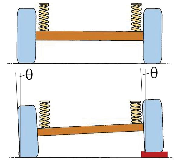
stabilizers
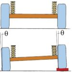
Elastic suspension has its downsides, and one of them is the tilting of the vehicle in a curve. In order to reduce tilting, stabilizer springs - stabilizers, usually torsion bars - are used. Mechanical torsion stabilizer is simple in construction, inexpensive and requires no special maintenance. It is mainly made in the form of a double lever and the clips are tied to the suspension system, and to the body of the vehicle is tied with metal rubber elements. The role of the stabilizer is to counter the tilting of the vehicle when one wheel of the same axle has deviations in the vertical direction from the other and counteracts the vertical movement of the wheel.
Text by Vanja Dragosavljevic
Audi Photos, www.howstuffworks.com
Retrieved from: www.vrelegume.rs
Recommendation of similar texts:


Hi there, I am Mladen and I am an auto enthusiast. I started this blog years ago to help like minded people share information about latest cars, car servicing ideas, used car info, exotic cars, and auto technology. You will find helpful articles and videos on a wide variety of cars - Audi, Mercedes, Toyota, Porsche, Volvo, BMW and much more. Ping us if you have anything cool to share on latest cars or on how to make older cars more efficient, or just want to say hi!
Mladen
Hi there, I'm Mladen and I'm an auto enthusiast. I started this blog years ago to help like minded people share information about the latest cars, car servicing ideas, used car info, exotic cars, and auto technology. You will find helpful articles and videos on a wide variety of cars - Audi, Mercedes, Toyota, Porsche, Volvo, BMW and much more. Ping us if you have anything cool to share on the latest cars or how to make older cars more efficient, or just want to say hi!