VTEC (Variable Valve Timing and Lift Electronic Control) system
 system")
VTEC (Variable Valve Timing and Lift Electronic Control) system
Before we begin the history of the emergence of this Honda system, we should explain the basic terms that define the operation of the engine.
For ordinary four-stroke internal combustion engines, the opening of the intake and exhaust valves is controlled by the camshafts. The shape of the cam determines the timing, the size of the lift and the duration of each valve. The valve opening time is defined by the crankshaft angle. In this case, the zero degree corresponds to GMT (upper deadlock TDC) and 180 degrees corresponds to DMT (lower deadlock BDC). The valve lift size refers to the height for which the valve is lifted from its seat. The duration of the valve opening is also defined by the crankshaft angular magnitude as well as the opening time, being the crankshaft rotation angle during which the valve is opened. Due to the properties of the mixture of fuel and air, the optimal operating parameters, ie. opening time, lifting size and duration of valve openings, in low engine rpm are completely different from those in high rpm. If the optimal parameters for low rpm in the high range were applied, the aim would be to under-fill the cylinders with a mixture and this would result in a drastic reduction in power. In the opposite case, the high rpm parameters would aim at overfilling the cylinders with a mixture and this would result in rough engine operation at low rpm as well as heavy duty operation at the unloaded state (on the so-called back). An ideal engine should have a completely variable opening time, lift size and duration of valve openings, in order to always open the valves at the right time, raise high enough and remain open long enough in relation to the engine rpm.
The VTEC story begins in the 400s in a Honda motorcycle. With the advent of the CBR XNUMXF, it was introduced REV (Revolution Modulated Valve Control) which at 8200 rpm allowed the engine to switch from 2 to 4 valves per cylinder. Models equipped with this system are the Honda CBR 400F and CBR 400F Endurance (399 cc, 58 bhp / 12,300 rpm). The REV system reconciled two incompatible things: quiet operation and good driving performance in the day-to-day use of a 2-valve engine per cylinder, as well as high power at high rpm two-valve engines.
 system")
 system")
In January 1983, a group of engineers was assembled to study the variation in valve timing to reduce fuel consumption. Already in October of the same year, the group was divided in such a way that the first group continued to address the problems of reducing consumption, while the second group worked to improve the valve timing. In March 1984, the first team launched its NCE program (New Concept Engine) with the aim of developing a generation of new engines that will feature high torque, both at low and high rpm with a significant increase in specific power. The success of the NCE program was proven in 1985, when Integra and Civic got DOHC engines that are fuel efficient and low in emissions, with plenty of torque and power (81 bhp).
At the time, Ikuo Kajitani was an engineer at Honda's Research and Development Center located in Tochigi. By contributing to the development of the engines mentioned above, he became convinced that the next generation of Honda engines should introduce a mechanism that would advance the variation in valve timing.
'' Find new technology that will drive the next generation of Honda engines '' - was a directive from the management of Honda's Research and Development Center. A moment that Kajitani used and led the project in the direction of his vision. As the increase in engine economy had already been realized, a new goal for the engineer group was to link exceptional economy with impressive power development throughout the rev range.
In November 1986, the idea of a new generation of engines was officially approved and established as the most important "D-development project". The launch of the new Integra, scheduled for early 1989, should also mark the start of their series production.
'' Four-valve engines are known as high-torque, powerful machines. For this reason, we knew it would be very difficult to perform well at low rpm if the engine volume was too small, '' Kajitani said. He also believed that expectations of 90 bhp, or 140 bhp from 1.6 liters of volume, would not represent the technological success expected of Honda in the 1.6s (Honda's current DOHC 130 liter engine already had XNUMX bhp).
'' Why don't you raise your target to 100 horses per liter? '' Were the words Nobuhiko Kawamoto, president of Honda's Research and Development Center, said to him. Inspired by the visionary proposal, Kajitani replied, "That will be our goal." Addressing his team of over a hundred engineers, he conveyed the decision to accept the challenge and set out the task of designing the Integrin 1.6-liter engine: 160hp and 8000rpm! Whatever the obstacles, it is something they must accomplish.
'' The engine is subjected to increased load if you increase its rpm, '' Kajitani said. '' So we had to keep in mind a 15-year or 250000-kilometer quality of use guarantee for this mass-production engine. ''
The team of engineers was immediately confronted with insurmountable problems, such as:
-8000 rpm is almost 20% higher than the maximum rpm achieved by current 1.6-liter DOHC engines (6800 rpm);
-inertial forces that will affect individual moving parts will increase by about 40%;
-naturally, the motor will be exposed to significantly higher voltages due to an increase in internal temperature;
- in order to reduce inertial forces within the engine at high rpm, the mass of each part must be reduced;
-if this is done, there will be problems with reducing the resistance of the material, which will call into question durability and reliability ...
The preparatory phase has begun and the team has identified about thirty new technologies and mechanisms that need to be introduced to provide a stable VTEC system. The evaluation committee carefully reduced that number to the extent necessary.
Variation in valve timing came into play only after evaluating the required valve diameter, the size of their lift, and the shape of the intake and exhaust ducts. Thus, e.g. the diameter of the intake valves relative to the current DOHC engine, increased from 30 mm to 33 mm, thus increasing the power over the entire rev range. Increasing torque at low rpm, which is one of the project guidelines, was achieved by reducing the crankshaft angle at which the cams in operation in this rpm range close the intake valves. Reduction from the usual 35 to 20/30 degrees NDMT (after the lower deadlock) allowed the intake valves to close faster, thus increasing the efficiency of the engine.
Also, the team adopted an opening time and a valve lift size (in the second phase of operation), similar to racing versions of Honda engines, which increased the efficiency of the engine volume utilization at high rpm. Additional measures have also been taken to reduce the suction resistance.
The pulley of low mass and low resistance to rotation is also one of the innovations. Made of high-pressure sintered metal alloy, this pulley had thinner walls than conventional ones. The moment of inertial forces is thus reduced by 10%. Due to all of the above, the load on the timing belt is drastically reduced at high power moments.
 system")
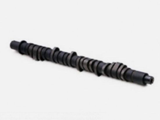
The implementation of new materials has certainly been a factor in the successful implementation of new technologies. For example. as the function of the VTEC system requires the placement of three cams in the space above each cylinder, both for the camshaft that controls the intake and the one that drives the exhaust valves, the camshaft width must be relatively small. This decrease leads to an increase in surface pressure. A new type of camshaft, chrome alloy steel with a high carbon content, is produced to undergo a combination of heat treatments and surface protections. The result is a camshaft whose hardness is increased by 40%.
 system")
 system")
Exhaust valves also required the use of newly developed steel alloyed with nickel, molybdenum, titanium and tungsten. High temperature resistance increased by 30%. Moreover, valves of increased diameter but therefore reduced tree thickness had a mass reduction of almost 20%. These ideas and efforts gradually shaped the reliable VTEC engine.
Metallurgy is one of the areas that Honda has learned very well through its sports-racing activities, culminating in the Formula One world. In fact, according to some sources, the chief engineer of the VTEC project was involved in the development of the F1 car, so experience was gained applied to a new type of engine that produces above average power and is exposed to higher thermal and mechanical stresses.
The engine block is made of aluminum. Steel guides are inserted in the process of casting it to increase the rigidity of the block. For the same reason, his transmission side is extremely reinforced. The back of the block is designed so that there is an oil cooler at the oil filter mounting point. The cooler is designed to allow the oil to deliver heat to the engine coolant. It has the form of a hollow torus through which coolant from the block circulates. As the oil passes through the radiator, the engine coolant lowers its temperature before it reaches the filter.
 system")
The forged steel crankshaft has eight counterweights designed to reduce inertial forces and vibrations at high rpm. In addition to the crankshaft, the largest moving parts of the engine are pistons and piston rods which, due to their movement mode, produce the greatest inertial forces. Particularly facilitated pistons and connecting rods have also been implemented in the new engine. The reduction of their mass was achieved by the design of thinner walls, which was made possible by the use of oil sprayers.

They are mounted on the block, and their task is to direct the oil jet towards the inner (lower) part of the piston and the piston rod and thus cool them. When the piston theme is cooler, it also has an effect on increased fuel combustion efficiency.

The new engine, along with the transmission, has almost 20 kg more weight than the previous ZC DOHC variant of the same volume. The increase in engine head mass is a modest 6.3 Kg, despite the increased number of cams, rockers and actuators.

However, the success of the development part of this project marked the beginning of a critical testing phase. It needed to ensure reliability and bring the product into the market without any doubt. VTEC technology, after all, should not have been limited to deployment in the new Integra alone, or as Kajitani was saying at the time: '' We were all determined to implement this technology in every Honda model. ''
In fact, at the beginning of the development of this engine, the biggest concern of the engineering team was the provision of all its functions. They knew that it would be difficult to guarantee the operation of a complex mechanism that makes the transition from one phase to another. For example. the selector pin has a diameter of only 10 mm, and therefore its operation may be limited by wear of only a few microns.
'' That's why we conducted our malware tests completely, '' Kayitani said. '' We were very close to the point of exaggeration. ''
The malicious test is designed to confirm the reliability and performance of an assembly by subjecting it to conditions far more difficult than expected during normal operation. In the case of VTEC, innumerable tests have been repeated repeatedly for vital parts such as the timing belt, camshafts, rockers, and phase selection shafts. These tests succeeded in meeting the goal of 400000 transitions from one engine mode to another. The team even conducted and analyzed the effects of tests in which the load increase was performed on the operation of the VTEC mechanism. Hydraulic and electrical systems have been accompanied by measures called 'fail-safe'. These are the measures in which an auxiliary device or system is used to ensure continued operation when a failure occurs in the mechanism. This not only eliminated the initial fears about the reliability of the system, but raised it to a level far higher than planned.
In April 1989, equipped with a DOHC VTEC engine designated "B16A", the new Integra was introduced. VTEC technology has been celebrated as the first system in the entire automotive industry to be able to simultaneously vary opening times and valve lift sizes, both on the intake and exhaust sides. Impressive specific power of a whopping 100 horses per liter, 8000 rpm, superior low rpm performance including idle, Honda's 'easy start', all while increasing fuel economy. It was the right dream machine for lovers of high
The real strength of VTEC is that it is extremely reliable. According to Top Gear, Honda has produced over 15 million VTEC-equipped cars and none of them have canceled or made any complaints about its performance during the warranty period.
'' We are all committed to doing our best to create the best engine in the world. We were convinced that variable valve timing technology would make tremendous progress. After all, we had to overcome the challenges of development and testing because we knew that only our great effort could bring this technology '' - words spoken by Ikuo Kajitani on his own behalf and on behalf of a team of talented and courageous engineers.
VTEC has become a world-renowned synonym for revolutionary discovery in the world of internal combustion engines, unlike its creator, which unfortunately has remained quite unknown to the world.
In the 1s, Honda introduced the first navigation system in the world of automobiles, the first all-wheel-drive system, created the first car with an all-aluminum body, introduced the first direct-injection system into the motorcycle world, and perhaps its greatest success was writing a significant part Formula One histories with six consecutive constructor titles. From the foregoing, it can be concluded that the appearance of VTEC was not a surprise but a true reflection of Honda's superiority over other manufacturers.
Operating principle and variants of VTEC system
DOHC VTEC - Looking at the image of the "ordinary" Honda DOHC PGM-Fi engine, in this case the ZC variant, we notice that each pair of camshaft cams with their respective rockers are separated.
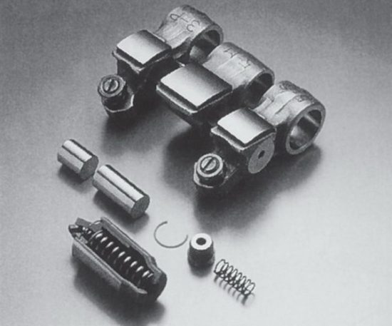
In the case of the DOHC VTEC variant, Honda placed another cam with a suitable rocker, between each pair of intake and exhaust valves.
Instead of one cam running each valve, there are now two: a moderate-profile cam optimized to increase engine efficiency at low rpm; a sharp cam built on a Honda racing engine to increase power at high rpm. The transition from one mode to another is controlled by the Engine Control Unit (ECU), which takes into account three factors:
- engine coolant temperature (must be greater than 60 degrees C),
- vehicle speed (above 30Km / h),
- engine speed (above 5500 rpm).
When the above conditions are fulfilled, a solenoid (valve) is activated which allows the oil pressure to move the shaft, which then connects the moderate profile rocker arms to the racing rocker. From that point on, the valves are driven by medium, sharp hills that "push" them deeper and keep them open longer. When the engine speed decreases, the solenoid returns to its original position, reducing the pressure of the oil acting on the shaft, so that it returns to its initial position by the action of the previously compressed coil spring. The movement of the rocker arms of the moderate and sharp cams is separated, so that the valves are again driven by the cams of the moderate profile. The VTEC deactivation speed is set to be below the activation speed to prevent the system from being switched on and off if the engine is held in that operating range.
 system")
Also note that DOHC (Dual Over-Head Camshaft) VTEC engines are equipped with moderate and sharp cam edges on both intake and exhaust camshafts, and thus the transition from low to high rpm is reflected by a real racing change sound. The 1.6-liter DOHC VTEC engine is the first to use VTEC technology. In April 1989, he first appeared in the Integra XSi and RSi, and in the fall of the same year was introduced in the Civic and CRX models sold on the domestic Japanese and European markets.
In 1990, the legendary was introduced Honda NSX with a DOHC VTEC V6 engine that produced 274hp. DOHC VTEC engines were later supplied by other models.
 system")
 system")
SOHC VTEC - This type of Honda engine is often mistakenly considered a second-class derivative of the DOHC VTEC, which is not really the case. It was designed to deliver enviable performance, with the only difference being that it had to do so with a single camshaft (SOHC-Single Over-Head Camshaft) that manages both intake and exhaust valves. As VTEC requires the use of a third centrally positioned cam and rocker (both for suction and exhaust valves), and in the SOHC engine, the spark plugs are positioned between the rocker valves of the exhaust valves, there is no space for the installation of the VTEC central rocker.
 system")
Because of this, the application of this technology is limited and used only for intake valves. The speed of these engines is also lower than that of the DOHC VTEC, so the transition from the first to the second phase of operation is performed at a lower 4800 rpm. As the mode changes only for the intake valves, this change is not reflected by the change in engine sound.
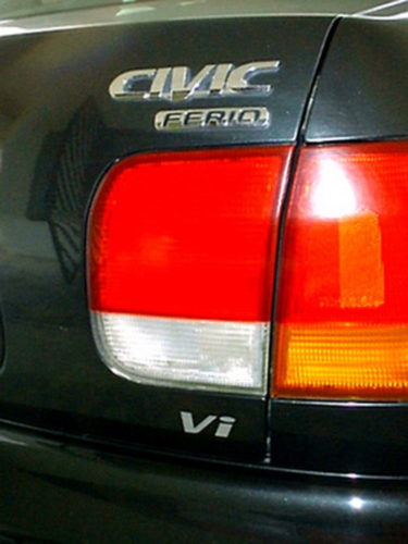
In 1991, the month of July was introduced as one of the first generators to boast this technology is the 15 liter D1.5B with an impressive power of 130 hp at 6800 rpm. He found himself e.g. in VTi models Civic, Ferio (1991-1999, Japanese market), as well as in CRX VXi EG1 (1992-1998, Japanese market).
SOHC VTEC-E - The next version of this Honda technology was used in a slightly different way. As the name of the system itself is called VTEC-E (VTEC-Economy), we conclude that it is not designed to improve performance but engine economy. At low rpm, one of the two intake valves is driven by a dam that allows it to barely noticeable lift. This way, in this mode, the unit runs in 12V mode (4 intake and 8 exhaust valves are active), forcing the engine to run with depleted mixture. In order to achieve a more efficient mixing of air and fuel in the cylinder, this unit uses the principle of air swirling in the cylinder.
 system")
When the rpm increases, both intake valves are required to supply the engine with the required mixture. An oil pressure driven shaft, as in other VTEC units, is used to connect the operation of the rockers that drive the valves. This will completely open the second suction valve and the engine now operates with all 16 valves.
This unit was found in several variants of the Civic as:
-D15Z1, 1992-1995 Honda Civic VX I VEi (European Market), 90 hp / 5600 rpm;
-D15Z6, 1995-2000 Honda Civic 1.5 iLS (European Market), 115 hp / 6500 rpm;
-D15Z8, 1997-2000 Honda Civic LS (European market), power 114 hp / 6500 rpm.
The consumption of the Honda Civic VEi in the city cycle is about 6l / 100Km, while the average consumption is below 5 liters.
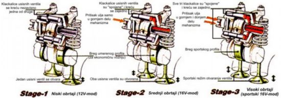
3-Stage VTEC - If we compare SOHC VTEC and SOHC VTEC-E implementations, we will see their similarity which led to the logical step of their merging. In other words, Honda has created an engine that meets the demands of those who want more power while reducing consumption.
The illustration below illustrates the principle of a 3 phase VTEC engine. It is equipped with two VTEC mechanisms that control the intake valve swingers. At low rpm (below 2500 rpm), no mechanism is activated, ie. the engine runs in 12V mode (one intake valve opens while the other is almost closed). This mode of operation is the most economical, as shown by the consumption of 3.3 l / 100Km when driven at a constant speed of 60 Km / h. If the accelerator pedal is pressed harder or 2500 rpm is exceeded, the VTEC mechanism on the top is activated and this is the beginning of the second phase. Now both valves are powered by a cam that provides economical running but in 16V mode which means the engine now has more power. The operation of the VTEC-E mechanism is actually described here. When the rpm exceeds 6000 rpm, the VTEC mechanism on the bottom is also activated, so that both intake valves are now driven by a medium, sharp bank. The engine has entered the third phase, producing the most power but at the expense of economy.
The v3-Stage VTEC was introduced in July 1995 along with an innovative automatic transmission called the Multimatic, all in a new, sixth-generation Civic. Labeled as D15B (D15Z7), it pulled out 1.5 hp at 130 rpm from 7000 liters of volume. It is easiest to identify by a pair of solenoids unlike other variants of systems that have a single solenoid.
 system")
He was able to blend incompatibly with the best economy with the highest power in his class! Between 1996 and 1999 it found itself in the Civic VTi and Ferio Vi models.
The essence of the 3-stage VTEC is the "power and economy" implemented on a 1.5l SOHC PGM-Fi engine. Many mistake the 3-stage VTEC as the superior evolution of the DOHC VTEC, describing the DOHC VTEC as an "older 2-stage VTEC" variant. This comparison is completely wrong because the DOHC VTEC was created solely for high specific power and sports-racing requirements.
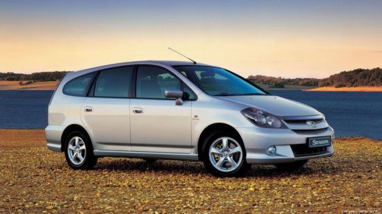
VTEC - On October 26, 2000, Honda announced a new generation of the so-called. of '' intelligent VTEC '' aggregates that will appear next (2001) with the new Stream.
Many innovations have been implemented, but the most significant is VTC (Variable Timing Control). This name hides the technology of a computer-controlled camshaft actuator capable of further rotating it by a 50 degree angle regardless of crankshaft rotation. This camshaft angle variation with respect to the crankshaft is performed using the oil pressure acting on the actuator. The entire mechanism is located at the end of the intake camshaft.
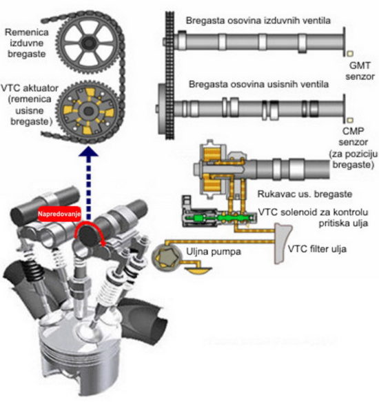
While for conventional motors, the link between the pulley and the camshaft is direct, with i-VTEC, a sloping-pinion gear is used as an intermediary in transmitting rotational motion. The pulley hub, which is a toothed wrench, and the aforementioned gear together form one internal gear pair. On the other hand, the intermediate gear is connected to the camshaft by a grooved joint in such a way that it allows axial movement relative to the camshaft. By pushing the oil on the intermediate gear, its axial movement is achieved, but because it is tied to the pulley by slanting teeth, this axial movement is converted into a rotational movement of the cams by a certain angle.
By varying the pressure of the computer-controlled oil, the cam rotation angle also changes, causing the valve overlap size to change. Valve overlap is the time interval when the intake and exhaust valves are open at the same time. The back of the cam (the phase of operation when the intake valves close earlier) reduces the size of the valve overlap, as opposed to the progression of the cam when the overlap increases.
Valve overlap plays a very important role in engine operation. Very little overlap gives the engine smooth running and good torque at low rpm, but disables engine performance at high rpm. Very large overlaps allow the engine to "breathe" at high, but cause rough running on the back and poor performance at low rpm. By varying the camshaft rotation and thus the size of the overlap, Honda's i-VTEC units have excellent performance in any mode. Also note that the operation of the VTC system depends on the load level of the engine, not just the speed.
The variable valve lift size was achieved through two rockers unlike earlier VTEC systems that used three rockers. With the new design, only one intake valve opens at low rpm, which improves the vortex of the mixture in the cylinder and thus optimizes combustion. At the programmed RPM, as with other VTEC variants, the oil pressure is used to "connect" the rocker arms and then both valves open together via a sharp cam.
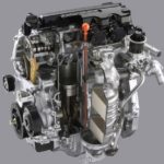
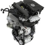
The most famous series of these engines is the K-series, which can be seen in two variants of the i-VTEC system: economical and sporty. Economical variant of this engine has the principle of operation as described above, ie. the intake camshaft has only two cams as there is no VTEC on the exhaust camshaft (similar to the SOHC VTEC-E). The sports variant is basically the same as the DOHC VTEC system in the B16A, and the intake and exhaust have 3 cams per cylinder.
 system")
However, this variant also has two accessories for valve timing relative to the B16A, namely roller rockers and the mentioned VTC on the intake.
 system")
These two engine variants are easily recognized by the power declared by Honda: the fuel-efficient variant produces no more than 160bhp, while the sporty one produces over 200bhp.
The K-series has found its place under the hood of several models such as the. Civic, Integra, Accord, CRV, Stream, and are available in 2.0, 2.3 and 2.4 liter volumes. Some examples of K-series variants and implementations are:
-K20A4, 2000-2003 Honda Stream (RN1), 154 hp / 6500 rpm;
-K24A3, 2003-2007 Honda Accord (Europe (EDM) and Japan (JDM)), power 190 hp / 6800 rpm;
-K20A, 2007-Honda Civic Type-R (FD2), 225 hp / 8000 rpm.
 system")
In September 2005, with the introduction of the next generation of Civic, Honda achieved the goal of equipping all models with advanced i-VTEC technology engines regardless of volume.
Photo: Wikipedia, Honda Forum
Written by: triodriver.com, Goran Zdravković - goranEE9
Retrieved from: www.triodriver.com
Recommendation of similar texts:


Hi there, I am Mladen and I am an auto enthusiast. I started this blog years ago to help like minded people share information about latest cars, car servicing ideas, used car info, exotic cars, and auto technology. You will find helpful articles and videos on a wide variety of cars - Audi, Mercedes, Toyota, Porsche, Volvo, BMW and much more. Ping us if you have anything cool to share on latest cars or on how to make older cars more efficient, or just want to say hi!
Mladen
Hi there, I'm Mladen and I'm an auto enthusiast. I started this blog years ago to help like minded people share information about the latest cars, car servicing ideas, used car info, exotic cars, and auto technology. You will find helpful articles and videos on a wide variety of cars - Audi, Mercedes, Toyota, Porsche, Volvo, BMW and much more. Ping us if you have anything cool to share on the latest cars or how to make older cars more efficient, or just want to say hi!
Can anyone tell me, "Honda stream" 2001 year
2.0 engine.
115kw, i-vtec, DOHC
It has ceramic or plain visible valves. Thank you.