Suction system on the engine

Suction system
About butterflies or air entry, in different ways

You've probably heard of the term "butterfly" in an engine and you've probably been confused by it. However, in our case, it is not about some winged creature that was created from a caterpillar, but about the part of the engine that is the first to react to the change in the position of the accelerator pedal (gas).
A butterfly that never took off
A butterfly is a (simplified) round plate that has a shaft set through its diameter. This plate is located inside the suction pipe, the purpose of which is to deliver air (or mixture) to cylinders, that is, to the intake ones of the valve. By pressing the gas, our "butterfly" rotates around its axis.
In fact, without that pressure, it is placed approximately vertically in relation to the suction pipe and thus leaks little (theoretically leaks nothing) air. However, by pressing the accelerator pedal, we turn the butterfly and it, the harder the pedal is pressed, lets in more and more air. The fully open butterfly is parallel to the suction pipe.
Butterfly housing depends primarily on the way the engine is refueled. As we will learn in later chapters, this method can be divided into three groups: carburetor fuel supply, indirect injection, and direct fuel injection. Yes, as in this story, there are "small million" subvariants, depending on the type of carburetor or injection system, but let's stick to the basics.
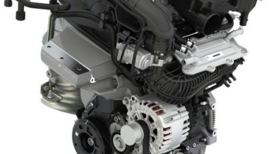
 - Initial Intake Manifold (Gray) (Skunk Racing)")
Butterfly housing position (silver) - at the beginning of the intake manifold (gray) (Skunk Racing)
In the case of a carburetor-equipped engine, the butterfly is integrated into the carburetor structure itself and is on the flow path of the mixture, therefore, after the point of entry of the fuel into the air stream. In the case of an engine equipped with both direct and indirect injection, the butterfly is in the path of the air flow, ie before the fuel injector.
In the case of diesel engines, fuel is delivered exclusively via injectors. Whether it is a system of a classic (now "old-fashioned") diesel engine with an attic or one with direct fuel injection into the cylinder, our butterfly will always be in the path of air flow, before the point of fuel injection.
And, let's not forget, before this whole "story" composed of suction, butterflies, carburetors or injectors, an air filter (purifier) is placed. We are of the opinion that its purpose should not be specifically clarified…

Suction branch compared to single suction
A branch that has never been in a tree
A suction pipe is a piece of metal (plastic or something similar) that leads air or a mixture of fuel and air to the cylinder. Due to the simplicity of construction, in the traditional construction of large series cars, this supply of air or mixture to the cylinders (suction valves) is solved so that the total amount of air needed to "supply" all cylinders comes through one pipe and then branches into as many pipes as there are cylinders. Such a suction system is called a suction branch.
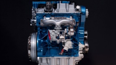
 compared to individual suction tubes that continue to separate butterflies (Skunk Racing, Kinsler)")
Suction branch (left) compared to individual suction 'tubes' that continue on separate butterflies (Skunk Racing, Kinsler)
The advantages of this construction are that it is enough to place one butterfly at the very beginning of the intake manifold (usually at the place where the air itself enters, before mixing with the fuel). However, the intake manifolds are often very complicated in shape and have a lot of curvature in the way of air flow. Of course, it is clear that these "bends" slow down the movement of air mass, which can ultimately lead to a lack of available air at high engine speeds.
The solution to this problem, which is more commonly used with high performance engines, is to install multiple standalone air intakes, each with its own butterfly. Although more complicated and expensive, this design provides significantly less resistance to air flow and thus makes the engine more efficient.
However, in addition to the curvature, the intake air flow velocity also depends significantly on the intake (intake) pipe intersection. Imagine trying to blow a pea grain through some slightly larger straw. After that, try the same, but take a 10 cm diameter tube. It is clear that the velocity of the air flow (which forces the grain) depends on the cross section, but in automotive engines (as many times before) it is necessary to find a compromise solution.
")
Variable Geometry Intake (Toyota Motor Co.)
Namely, the designs of today's intake systems must satisfy the need to supply the engine with air at all speeds of operation, so it is completely understandable that it is not possible to achieve an intake that is ideal in all operating conditions.
An increasingly popular solution that car manufacturers are trying to address is the variable geometry suction, which automatically changes the length of the suction ducts, given the engine speed and some other parameters. This change takes place under the supervision of a computer, and the most common technical solution is with the complex design of suction pipes (plastic system on the left, in our picture), which does not actually change the length of the suction in the physical sense, but the individual suction channels open or close to change the length of the path that air must pass through the intake.
 (BMW AG)")
Gasoline V8 S65 engine with eight single intake butterflies (pictured closed) (BMW AG)
Practice is, as always, something else…
Lastly, we should mention how fuel "looks" at our play with the speed of air intake. Namely, if the air flow is too slow, an effect can occur in which the fuel "falls" from the mixture. The air flow then does not have enough speed to carry small fuel particles and they fall on the walls of the intake ducts. This results in a large amount of unburned fuel which, in the final analysis, reduces engine power.
The other extreme occurs at extremely high engine speeds when the fuel does not have time to mix with the air in the mixture before it reaches the intake valve. In such a case, it is necessary to inject the fuel into the air stream as far as possible from the end of the intake, exactly the opposite of when we have a slower flow.
And to make everything even more complicated, we can add the topic of air temperature in the intake system to the story. Namely, we know that colder air is denser, which means that it contains more oxygen necessary for combustion of the mixture to a lesser extent. Therefore, the beginning of the intake system (the opening of the pipe that brings air to the filter) is placed as close as possible to the front of the vehicle, ie. "Masks". Precisely due to the difference in air density, there was a noticeable difference in performance on older engines, depending on the ambient temperature. For colder days, the engines somehow worked better. However, due to the longer time required to reach the optimal operating temperature, the consumption of oxygen-rich fiber (per unit volume) was not lower, moreover.
For fun, for example, on the surface of the sea (zero altitude), at a temperature of 20 ° C, the air has a density of 1,2041 kg / m3 (the share of oxygen in the air is 20,95%). It should be taken into account how the air density, in addition to the influence of temperature, changes depending on the altitude. Thus, without precharging (turbocharger), ie. introduction of air into the intake at a pressure higher than atmospheric, the drivers of the Dakar rally crossing the 4750 m high pass Paso de San Francisco was quite difficult.
As we can see, compromise was again one of the keywords. The ideal engine, which would work most efficiently under all operating conditions, of course, does not exist. But today's systems (such as variable geometry intake) have run into many problems that have plagued engines of the past.
")
ETC Butterfly Bosch DV-E (Robert Bosch GmbH)
Highlights - Drive by Wire
The butterfly that controls the flow of air in the car's intake system in classic constructions is driven by a steel rope (cable). This rope, in fact, represents the mechanical connection between the accelerator pedal (gas) and the butterfly itself. Whether the connection is made directly or via a transmission system, this method of suction control uses a return spring that returns the butterfly to the closed position (no air flow) when the accelerator pedal is released. Such a classical system "suffers" from several shortcomings of a mechanical nature. The most common problems that can occur are sticking of the steel rope caused by impurities, stretching that occurs over time, cracking as a result of wear and the like.
")
Drive-by-Wire accelerator pedal with programmable position sensor (Lokar Performance Products)
The ETC and electronic (electrical) connection between the accelerator pedal and the fuel injection system together make the assembly popularly called Drive-by-Wire in which the mechanical connection between the accelerator pedal and the engine control is replaced electronically.
ETC systems are (theoretically) more reliable and respond more precisely to changes in accelerator pedal pressure. As a rule, they are also equipped with a butterfly position sensor (usually a magnetic sensor). The electronic gas system is protected from potential failures that would e.g. could cause a constantly open butterfly, regardless of the driver's influence, ie. driving "at full throttle" without the driver depressing the pedal at all.
The protection consists in the sight Safe-fashion which is triggered if the flow of information in the relation between the accelerator pedals - the monitoring computer - the butterfly is interrupted or if an error occurs in that information which causes a problem in the communication between the mentioned systems. The so-called Safe mode as a rule, the computer keeps the throttle open only so long that the engine is not in idle mode, and that you can reach the destination at a minimum speed, of course.
In this video showing a Hyundai NU petrol engine, the variable geometry intake mode is visible:
author: AUTONET.HR
Recommendation of similar texts:


Hi there, I am Mladen and I am an auto enthusiast. I started this blog years ago to help like minded people share information about latest cars, car servicing ideas, used car info, exotic cars, and auto technology. You will find helpful articles and videos on a wide variety of cars - Audi, Mercedes, Toyota, Porsche, Volvo, BMW and much more. Ping us if you have anything cool to share on latest cars or on how to make older cars more efficient, or just want to say hi!
Mladen
Hi there, I'm Mladen and I'm an auto enthusiast. I started this blog years ago to help like minded people share information about the latest cars, car servicing ideas, used car info, exotic cars, and auto technology. You will find helpful articles and videos on a wide variety of cars - Audi, Mercedes, Toyota, Porsche, Volvo, BMW and much more. Ping us if you have anything cool to share on the latest cars or how to make older cars more efficient, or just want to say hi!
Does the a4 2.0 diesel have that suction flap open all the time