Alternator - Alternator repair - procedure

Alternator
First, the pulley is removed from the alternator. The thread must first be sprayed with WD, and with the help of the wrench 24 and the hexagon 8, to secure the shaft, remove the pulley below.

Then we remove the back protective plastic held by 3 screws.

When we remove the plastic, we immediately see the regulator with the brushes on the plastic holder and the diode bridge.

We remove the controller by unscrewing the small screws that hold it in this case. It was necessary to remove the nut from the longest screw that would normally come from the battery cable.

The brushes are sometimes beneath a small plastic cover that is removed and then the cans on which the brushes are soldered are seen. The brushes are welded on some alternators, simply cutting off the braided wire and fixing the wires with new brushes.

New brushes.
In order to remove the rear part of the housing, we have to unsolder the wires of the stator terminal which is part of the front housing of the alternator. The wires are soldered and pressed with the contact sheet, so they should be desoldered at the same time and the plates should be spaced with a flat-blade screwdriver. There are 3 terminals with 2 wires on each contact.

The rear part of the housing on which the diode bridge with three screws was screwed was removed.
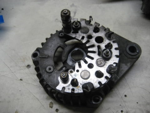
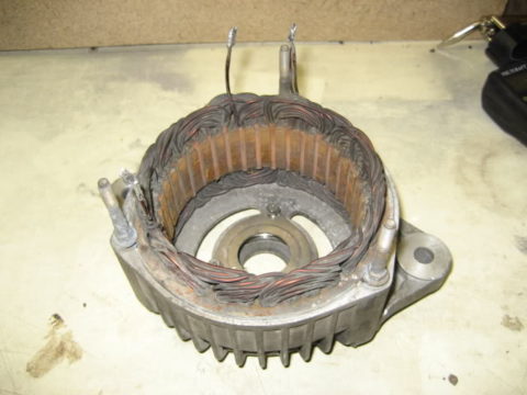
The front of the case with the stator and its terminals - 3 times two wires.
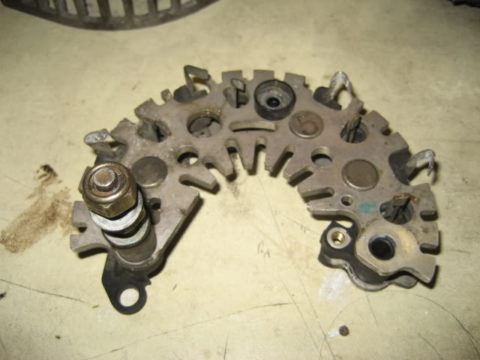
Remove the diode bridge.
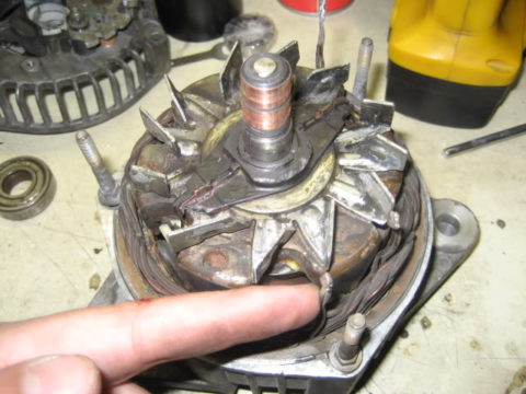
The rotor is knocked out slightly, the front larger bearing remains in the housing, and the rear remains on the rotor shaft.
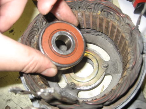
The front part of the housing with the stator, the bearing is located under the cover which is fixed with three screws.
A closer look at the front evening bed in its bunk.
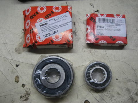
New bearings.
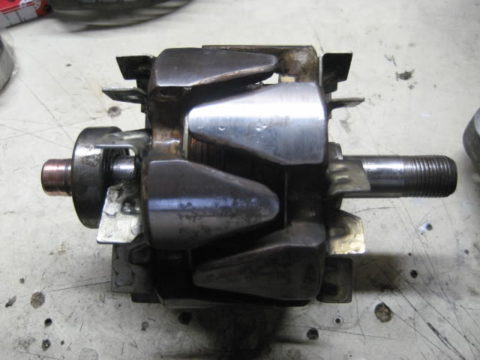
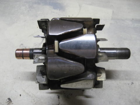
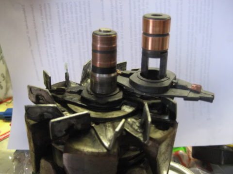
Rotor with rear bearing removed.
The assembly goes in the reverse order: put the rear bearing, put the front bearing in its bearing and screw the bearing cover. We place the rotor inside the front part of the housing with the stator and "charge" it through the front bearing to the end. Screw in the back of the case, screw in the diode bridge and solder the leads. Return the regulator and the holder with the new soldered brushes to its bearing and screw it on. Fasten the rear protective plastic with 3 screws. Screw in the pulley nut holding the shaft with an Allen key.
The only thing that is desired to be done is to align the grooves on the rotor collector, ie. those two copper rings at the end of the rotor are grooved, so that in order for the new brushes to "lay down", these copper rings are aligned - either they are out of shape or if they are not large grooves, they are slightly sanded while turning the rotor.
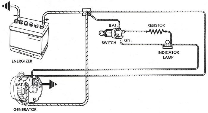
PRINCIPLE OF WORK OF ALTERNATOR
As can be seen from the attached, the alternator stator has three coils in which AC is induced, so the alternator in its first stage is an AC generator of about 120V (when the rotor would constantly get 12V, ie it would be max. Magnetized).
Why three coils?
Due to the so-called voltage ironing - each cycle has one peak or a peak with three coils, these peaks are smoother, it would be ideal to have as many coils as possible, but that would of course complicate the construction of the alternator.
In order to induce current in the coil, a magnet must pass through it, in this case it is the electromagnet of the rotor that receives current through the regulator brushes.
The REGLER is connected to the stator and rotor of the alternator at the same time. It is an electronic circuit that is factory set to regulate the alternator voltage to some 14-15V, and it works on the principle of measuring the stator voltage, if it falls, it simultaneously amplifies the voltage in the rotor which becomes more magnetized and increases the voltage and current in the stator. If the voltage increases, it reduces the rotor voltage and maintains the voltage within the limits for which it was made. This is most pronounced when changing the engine speed, and thus the speed of the alternator itself.
We have to keep in mind that the alternator itself has several times smaller pulley than the crankshaft pulley through which it is driven, and thus the alternator revolutions are several times larger than the engine speed.
So we have three-phase AC voltage at the stator terminals. These leads are connected to 3 times two rectifier diodes on a diode bridge where the three-phase alternating voltage is converted into a "single-phase" direct current of some 14 V required for the operation of the device in the car.
Alternators differ in the maximum current they can give under peak loads, in this case it is 85A at 14V. Of course, there are stronger and weaker alternators, depending on the car model and the amount of devices in the car.
The most common failures of alternators are worn out brushes, the battery-shaped indicator light on the instrument panel lights up, the car lights harder until it finally lights up, because without generating electricity from the alternator, all the electricity is drawn from the battery.
Another rare breakdown is the overheating of diodes or one of them. This is most often due to the excessive consumption of current that the alternator can deliver (eg loud music) or dust that prevents the cooling of the diodes. In this case, the battery does not charge again and the instrument panel light illuminates or flashes.
The third most common malfunction is the buzzing of the bearings, most often the front which is the most loaded, as it takes over the force of the tensioned V-belt over the pulley and the water and moisture that can get into the bearings due to damaged bearing seals.
The rarest failures are the overheating of the stator coil or even less often the rotor which is again due to overload.
The replacement itself is simple, disconnect the wires from the impeller, the manifold breaks out and inserts the new one back with light strokes until it snaps into place. The wires are connected back to the collector contacts.
Retrieved from: www.fiatisti.hr


Hi there, I am Mladen and I am an auto enthusiast. I started this blog years ago to help like minded people share information about latest cars, car servicing ideas, used car info, exotic cars, and auto technology. You will find helpful articles and videos on a wide variety of cars - Audi, Mercedes, Toyota, Porsche, Volvo, BMW and much more. Ping us if you have anything cool to share on latest cars or on how to make older cars more efficient, or just want to say hi!
Mladen
Hi there, I'm Mladen and I'm an auto enthusiast. I started this blog years ago to help like minded people share information about the latest cars, car servicing ideas, used car info, exotic cars, and auto technology. You will find helpful articles and videos on a wide variety of cars - Audi, Mercedes, Toyota, Porsche, Volvo, BMW and much more. Ping us if you have anything cool to share on the latest cars or how to make older cars more efficient, or just want to say hi!
The electrician said that it was not worth repairing the alternator and I bought a new one and put it in. immediately after the first ignition, the car does not reach normal revs in the back, but starts at about 500 rpm and needs 3-4 seconds to gradually accelerate to about 800 rpm and then the control (red battery) goes off.
before the alternator was changed there was no problem, the car started normally.
when it reaches normal revs in the back, the engine runs smoothly and evenly, it does not jerk while driving, ie everything is normal.
what could be the problem?
bad ack, clamps