Crankshaft - what is it for - Technique

Crankshaft (Crankshaft)
From straight to circular

Main parts of crankshaft
The crankshaft, or "crankshaft", is one of the larger one-piece components of an internal combustion engine. The role of the crankshaft is in the transmission of power from the pistons to the transmission system of the vehicle (specifically, to the gearbox).
And, since all the drive parts of the transmission move in a circular fashion, on the output part of the engine (the part that will transmit power or moment to the transmission system), we have to get something like this in a circular motion, although we got the engine power thanks to the straight-line movement piston (complicated enough and incomprehensible explanation, right?))
")
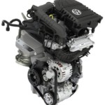
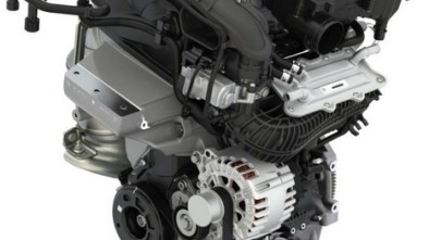
Connecting Rods and Crankshaft (Mopar - Chrysler Group LLC)
An invention that makes everything spin
The crankshaft is made of one piece of steel and is usually cast or sparse, forged and subsequently machined to make bearing bearings, holes and grooves, and front and rear extensions. The energy that develops through the combustion of a mixture of fuel and air pushes, as we know, the piston toward DMT. A piston rod is attached to it, which is the connection between the piston and the crankshaft.
The lower part of the connecting rod consists of two parts that form a round opening inside which there is a bearing. That, the lower part of the connecting rod is attached to the crankshaft on which there is a bearing with a lubrication hole. Thus, the connection of movement between the connecting rod and the crankshaft is realized, which is necessary in order to translate the rectilinear movement of the piston, through the connecting rod, into a circular movement of the crankshaft.
")
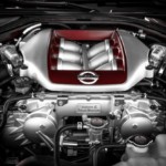
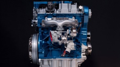
Forged V8 Engine Crankshaft (Mercedes-Benz AMG)
On the opposite side of the piston rod bearings are a counterweight that ensures the engine runs evenly. These weights have the task of balancing piston and piston rod motion, which slows down engine performance and allows for safe operation at higher speeds (rpm). The weights are usually made in one piece, together with the crankshaft and subsequently machined to balance their weight, but sometimes the counterweights are bolted.
Of course, proper lubrication of the bearings on the crankshaft bearings is also significant because of the great force that pushes the piston (although the characteristics of today's propulsion machines differ drastically, only illustrations can say that some typical value for petrol engines is up to 18.000 N).

 bearings with lubrication holes - 6,2-liter V8 engine LT-1 from Corvette Stingray (General Motors)")
Piston with connecting rod and several (two-part) bearings with lubrication holes - 6,2-liter V8 engine LT-1 from Corvette Stingray (General Motors)
What drives the crankshaft?
At the ends of the crankshaft, there are extensions for attaching vibration dampers, pulleys, flywheels, etc. On the front (conditionally speaking) side of the engine is the end of the crankshaft to which the vibration damper is attached. It is an insert with metal and rubber parts intended to dampen vibrations (which moves the crankshaft longitudinally). Its role is primarily to "calm" the crankshaft enough so that it does not break or be damaged in any other way due to overload. Also, at the same end of the crankshaft, there are extensions for connecting pulleys that drive the water pump, alternator, camshafts and more.
Also, on the so-called a disk for measuring the speed of rotation is mounted on the front part of the crankshaft. Such a disk is made either in the form of gears or has holes (recesses) around the rim. An optical (or magnetic) sensor located next to this disc sends information to the engine's central control computer about the speed of the teeth or holes. This data is then converted into engine speed (crankshaft speed) which is one of the basic parameters required for the operation of the electronic control system. With this information, the engine "knows" at what point the spark should be given to the spark plug, when it is necessary to start the fuel injection, etc.
 whose crankshaft is mounted in 6 bearings (Daimler AG)")
The crankshaft always has one bearing more than the in-line cylinder engine. In this case, it is a 5-cylinder engine from Mercedes-Benz 240 D (1974) whose crankshaft is mounted in 6 bearings (Daimler AG)
On the other side (literally "rear" side of the engine) of the crankshaft, there is an extension to which the flywheel is attached. The flywheel is a round metal disk which, with its inertia during rotation, moves the crankshaft over the so-called "Dead piston points" and empty idle clocks, thus maintaining a constant rotational speed. This dampens vibrations and ensures even engine operation. The flywheel is characterized in that it has teeth arranged on its circumference that rest on the gear of the electric starter motor.
Is there a story for those "who want to know more?"
There are almost no special "variations on the theme" in the story of the crankshaft. The only differences are in the number of bearings with which the crankshaft is attached to the engine block and in the material from which it is made, as well as the size of the counterweight. It is clear that in high-performance engines (sports cars), an attempt is made to reduce the mass of moving parts as much as possible in order to facilitate work and increase the highest number of revolutions.
Such motors are usually equipped with crankshafts with small and light counterweights and a significantly lighter flywheel. Certainly, at low speeds, the engine processed in this way will shake quite a bit, which is tried to be avoided in large-series vehicles. Another variation is the V engine crankshaft. These engines have two connecting rods (opposite pistons) connected to one, extended knee seat. Sometimes the seats of the V engine are made as a double, with a small (eccentric) distance in order to achieve a better distribution of forces.
")
Shaft-driven vibration canceling shaft (Saab AB)
Vibration canceling shafts
In order to further cancel the vibrations generated by the operation of the internal combustion engine, vibration canceling shafts have been devised. It is the invention of the English engineer Frederick W. Lanchester of 1904, who will experience practical application in car engines many decades later. Such shafts are most commonly encountered in 4-cylinder in-line engines, where vibrations cannot be canceled out solely by precisely balancing individual moving engine parts. Namely, 4-cylinder in-line motors are particularly problematic with respect to vibrations because the piston rod movement is not symmetrical with the rotation of the crankshaft (pistons moving towards DMT or GMT are not always symmetrical, ie not equally distant from the upper or lower end positions).
The vibration damping system usually consists of two axles that rotate in opposite directions, at a speed twice the speed of the engine (crankshaft rotation speed). On these axes there are eccentric weights (of equal mass) whose inertial reaction (due to opposite directions of rotation of the axles) is canceled on the horizontal plane, but adds up on the vertical. This is exactly the direction in which the vibrations caused by the uneven movement of the pistons occur.
As expected, the problem of such vibrations is especially significant with 4-cylinder engines of larger volumes (as a rule, above 2000 cm3). That's why Porsche used two anti-vibration axles that rotated in opposite directions on its 2,5 4-liter 944-cylinder in-line 1982 in-line engine. It was one of the first known examples of using this method of solving the problem of vibrations in a car engine. However, the concrete design for vibration cancellation using special axles was patented by Mitsubishi in 1975. The commercial name of this construction was called Silent Shaft, and it was first used in 4-cylinder in-line engines of the G45 series (Astron 80).
Of course, it is clear that by changing the design of the engine, such vibrations can be reversed without the use of calming axles or any other similar method. One of the most favorable constructions in that sense is a boxer, or engine with an angle between the rows of cylinders of 180 degrees. Also, engines with V-cylinder cylinders are less susceptible to such vibrations, especially those with a larger number of cylinders. After all, some may even remember the anecdote in which Ferruccio is Lamborghini placed an egg on the valve cover of his V12 engine to prove how quietly the machine was running. Of course, the egg didn't even move 🙂
Author: AUTONET.HR
Retrieved from: www.autonet.hr
Recommendation of similar texts:


Hi there, I am Mladen and I am an auto enthusiast. I started this blog years ago to help like minded people share information about latest cars, car servicing ideas, used car info, exotic cars, and auto technology. You will find helpful articles and videos on a wide variety of cars - Audi, Mercedes, Toyota, Porsche, Volvo, BMW and much more. Ping us if you have anything cool to share on latest cars or on how to make older cars more efficient, or just want to say hi!
Mladen
Hi there, I'm Mladen and I'm an auto enthusiast. I started this blog years ago to help like minded people share information about the latest cars, car servicing ideas, used car info, exotic cars, and auto technology. You will find helpful articles and videos on a wide variety of cars - Audi, Mercedes, Toyota, Porsche, Volvo, BMW and much more. Ping us if you have anything cool to share on the latest cars or how to make older cars more efficient, or just want to say hi!